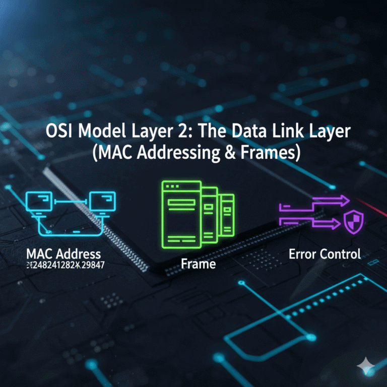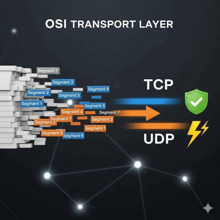
We’ve completed an incredible journey through the OSI Model! We’ve seen applications create data, the Presentation Layer (Layer 6) format it securely, the Session Layer (Layer 5) manage conversations, the Transport Layer (Layer 4) ensure reliable delivery, the Network Layer (Layer 3) route it globally, and the Data Link Layer (Layer 2) handle local transfers. Now, we arrive at the absolute bedrock of all network communication: Layer 1, The Physical Layer.
This is where the digital world of 0s and 1s transforms into the tangible realm of electrical signals, light pulses, or radio waves.
Think of the Physical Layer as the fundamental engine and infrastructure. If the Data Link Layer is your local delivery service, the Physical Layer is the actual road, the delivery vehicles, the fuel, and the traffic lights – everything physical that makes movement possible. It’s solely dedicated to the raw, unadulterated transmission of bits across a physical medium.
Key Functions of the OSI Physical Layer
The Physical Layer defines all the essential specifications for activating, maintaining, and deactivating the physical link between networked devices. Let’s explore its critical responsibilities.
1. Physical Characteristics: The Hardware You Can Touch
This layer meticulously specifies the physical components of your network. It’s about the “what” and “how” of connections:
- Cables & Connectors: What type of cabling is used (e.g., copper Ethernet cables like Cat6, glowing fiber optic cables, or older coaxial cables)? What are the specific RJ45 connectors like?
- Network Interface Cards (NICs): These are the hardware cards (or integrated chips) in your computer, server, or smartphone that allow it to physically plug into or connect wirelessly to a network.
- Networking Devices: Simple devices like hubs and repeaters operate strictly at Layer 1, merely regenerating and boosting signals.
- Physical Topologies: This layer dictates the actual physical layout of devices and cables (e.g., star, mesh, bus, ring configurations).
2. Bit Representation: Digital to Analog Conversion
The Data Link Layer hands down logical “0s” and “1s.” It’s the Physical Layer’s job to translate these abstract bits into tangible physical signals that can travel:
- Electrical Signals: For copper cables (like Ethernet), bits are represented by varying voltage levels.
- Light Pulses: For fiber optic cables, bits become rapid flashes of light.
- Radio Waves: For wireless connections (like Wi-Fi), bits are encoded into electromagnetic waves.
This crucial encoding process ensures that the raw binary data can physically traverse the chosen network medium.
3. Data Rate: How Fast Data Travels
This layer defines the data rate, which is simply how fast data can be transmitted across a given link. Measured in bits per second (bps), this determines your network’s speed (e.g., 100 Mbps, 1 Gbps, or even 10 Gbps and beyond). It also sets limits on how far a signal can travel before it degrades and needs boosting.
4. Synchronization of Bits: Keeping in Time
For data to be accurately interpreted, both the sending and receiving devices must operate in perfect unison. The Physical Layer manages the synchronization of bits by establishing a common clocking mechanism. This precise timing allows the receiver to correctly identify the start and end of each bit, preventing misinterpretation of the incoming raw data stream.
5. Transmission Mode: The Direction of Flow
The Physical Layer also specifies the direction and capacity of data flow on the physical link:
- Simplex: Data travels in only one direction (e.g., a traditional radio broadcast).
- Half-Duplex: Data can flow in both directions, but only one direction at a time (like using an old walkie-talkie).
- Full-Duplex: Data can flow simultaneously in both directions (the standard for modern Ethernet and Wi-Fi connections).
Conclusion: The Unseen Foundation of Connectivity
The Physical Layer is the essential, often unseen, backbone of all network communication. It’s where the abstract world of computing meets the tangible reality of physics, converting digital information into physical signals that traverse our cables and airwaves. Without its precise specifications for hardware, signals, and timing, no other layer of the OSI Model could function.
The OSI Model: A Unified Framework for Understanding Networks
Congratulations! You’ve now completed our deep dive into all seven layers of the OSI Model. From the applications you use every day (Layer 7) down to the very wires and signals that carry the bits (Layer 1), each layer plays a specific, vital role, building upon the services of the layer below it.
This layered approach beautifully illustrates encapsulation – how data from a higher layer gets wrapped with control information as it moves down the stack – and de-encapsulation as it travels back up.
Understanding the OSI Model isn’t just theoretical; it’s a fundamental skill for anyone working with networks. It helps you troubleshoot issues, design robust systems, and build a strong foundation in both networking and cybersecurity.
Thank you for joining us on this comprehensive journey into the architecture of the internet! We invite you to explore more foundational cybersecurity and networking topics right here on CyberTerminal.tech!
What part of the Physical Layer do you find most fascinating? Share your thoughts in the comments below!
Ready to get your hands dirty? Subscribe to CyberTerminal to stay updated!
[INSERT_ELEMENTOR id=”1346″]